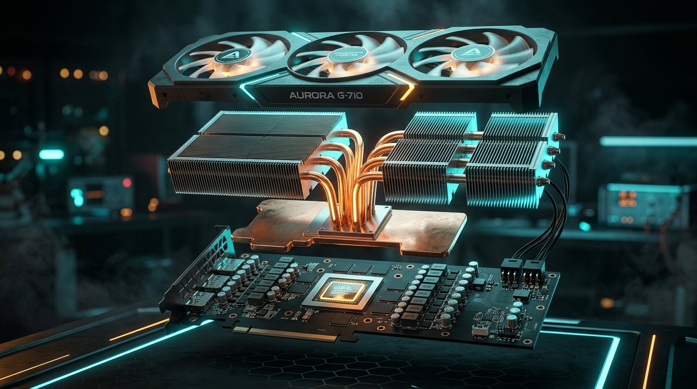
Interactive 3D Studio: Explode GPU Heatsink
Run exact formula simulations on NexProTools.
In modern high-performance computing and gaming architectures—headlined by flagship architectures like NVIDIA Ada Lovelace, Blackwell, and AMD RDNA 3/4—thermal engineering has evolved from a secondary packaging concern into the primary determinant of sustained silicon performance.
When an enthusiast installs a modern flagship graphics card, they are mounting a miniature thermodynamic power plant into their chassis. GPUs routinely draw between 300W and 550W of continuous board power, with transient microsecond current spikes pushing power delivery circuits well beyond 600W.
Yet, despite massive heatsinks occupying 3.5 to 4 PCIe slots and weighing in excess of 2.2 kilograms, many users observe perplexing thermal phenomena:
- Core temperatures remain comfortably at 62°C, yet the VRAM Hotspot spikes past 95°C.
- Mounting a graphics card in a vertical PCIe orientation suddenly causes temperatures to drift upward by 8°C to 14°C.
- High-end cards featuring 9 composite heatpipes struggle to match custom models engineered with a flat planar vapor chamber.
Why does a vapor chamber outperform discrete heatpipes? How do phase-change cooling loops function inside a vacuum-sealed copper envelope without any moving mechanical parts? And what governs the thermal conductivity between silicon micro-dies, thermal interface materials (TIM), and aluminum dissipation fins?
In this exhaustive engineering treatise, we dissect the internal physics of modern GPU thermal architecture using our interactive 3D anatomy engine.
1. The Physics of GPU Thermal Density: Why Air Cooling Hit the Wall
To understand why modern graphics cards require exotic cooling architectures, one must first analyze thermal density (heat flux) rather than gross thermal output.
A typical domestic space heater consumes 1500W of electrical power. However, that 1500W is dissipated across a heating element spanning over 2,500 square centimeters (cm^2), resulting in a modest heat flux of roughly 0.6 W/cm^2.
By contrast, an NVIDIA AD102 processor (the silicon core of the GeForce RTX 4090) measures exactly 608.5 mm^2 (6.085 cm^2) and operates at sustained continuous loads of 450W:
HEAT FLUX DENSITY COMPARISON
- AD102 GPU Core (450W / 6.085 cm²): ~73.9 W/cm²
- High-Performance CPU (250W / 1.80 cm²): ~138.8 W/cm²
- Commercial Nuclear Reactor Core Fuel Rod: ~65.0 to 100.0 W/cm²
- Domestic Electric Space Heater: ~0.6 W/cm²
This extreme thermal concentration creates a massive localized heat flux. The primary challenge in cooling modern silicon is not simply radiating heat into the ambient air, but spreading concentrated heat away from a microscopic 6 square centimeter die across a massive 2,000 square centimeter aluminum fin assembly before thermal bottlenecking induces silicone throttling.
2. Fundamental Governing Laws of Conduction and Dissipation
All GPU thermal architectures operate under three fundamental thermodynamic equations:
Fourier's Law of One-Dimensional Heat Conduction
Within solid materials (copper cold plates, silicon dies, and aluminum heatsink fins), heat transfer occurs via conduction:
Where:
qis the heat flux vector (W/m^2).kis the intrinsic thermal conductivity of the material (W/m· K).∇ Tis the spatial temperature gradient (K/m).
Convective Heat Transfer (Newton's Law of Cooling)
Once heat reaches the outer surfaces of the aluminum cooling fins, it must be rejected into moving air propelled by axial fans:
Where:
Qis the total heat rejection rate (Watts).his the convective heat transfer coefficient (W/m^2· K), determined by air velocity, turbulence, and boundary layer thickness.Ais the total active surface area of all cooling fins (m^2).T_s - T_∞is the temperature difference between the aluminum fin surface and ambient intake air.
The Spreading Resistance Barrier (R_spread)
When heat transfers from a small heat source (the GPU die, area A_die) to a substantially larger heat sink base (area A_base), heat does not travel purely downward; it spreads outward in three dimensions.
In solid copper, this 3D spreading induces a severe thermal spreading resistance (R_spread). As heat travels laterally through solid metal, each additional millimeter of distance increases thermal resistance proportionally to the path length divided by cross-sectional area:
Even though pure copper boasts an impressive thermal conductivity (k ≈ 390 - 400 W/m· K), a solid copper plate 5mm thick quickly chokes when trying to spread 450W laterally over distances greater than 50mm. This geometric bottleneck is precisely where two-phase liquid-vapor transitions revolutionize cooling.
3. How a Vapor Chamber Works: Phase-Change Thermodynamics
A vapor chamber is a hermetically sealed, vacuum-pumped copper vessel containing a specialized inner capillary wick structure and a high-purity working fluid (typically deionized water).
Because the internal chamber is evacuated to an extreme vacuum (roughly 0.005 to 0.01 atmospheres / 0.5 - 1.0 kPa), the boiling point of the enclosed water drops dramatically from 100^\circC down to 28^\circC - 35^\circC.
THE FOUR STAGES OF THE VAPOR CHAMBER THERMAL CYCLE
- Evaporation Phase: Heat from the GPU die conducts through the microscopic copper chamber wall into the evaporator wick, instantly vaporizing the working fluid into high-energy gas.
- Sonic Vapor Expansion: The high-pressure vapor accelerates toward the cooler regions of the chamber at speeds reaching hundreds of meters per second, distributing thermal energy isotropically across the entire 2D plane.
- Condensation Phase: Upon contacting the cooler condenser wall bonded to the fin stack, the vapor releases its latent heat of vaporization (
~ 2,260 kJ/kg) and condenses back into liquid droplets.- Capillary Pumping Return: Sintered copper microscopic wicks generate massive capillary suction pressure, pulling the liquid coolant back to the evaporator over the GPU die.
| Metric / Attribute | Solid Copper Plate (6mm) | 6x Heatpipe Array (Direct) | Planar Vapor Chamber |
|---|---|---|---|
Effective Thermal Conductivity (k) | 390 W/m· K | 4,000 - 8,000 W/m· K | 10,000 - 25,000 W/m· K |
| Spreading Geometry | 3D Radial Conduction | 1D Axial Lines | 2D Full Planar Diffusion |
Thermal Spreading Resistance (R_spread) | 0.12 - 0.18 K/W | 0.08 - 0.12 K/W | 0.03 - 0.05 K/W |
| Hotspot Temperature Delta | High (18 - 25^\circC) | Medium (10 - 15^\circC) | Minimal (4 - 7^\circC) |
| Weight per Surface Area | Extremely Heavy | Lightweight | Moderate |
| Manufacturing Cost | Low | Low to Moderate | High (Precision brazing & vacuum seal) |
4. Heatpipe Internal Anatomy: Sintered Powder, Grooves, and Meshes
While a vapor chamber acts as a planar 2D expansion plate, cylindrical heatpipes act as directional 1D thermal highways, transporting thermal energy from the baseplate into distant fin stacks.
Not all heatpipes are created equal. The performance of a heatpipe is primarily determined by its internal wick structure:
1. Sintered Copper Powder Wicks (Esports Standard)
Sintered wicks are fabricated by packing spherical copper powder granules (50 - 100 microns in diameter) around a central mandrel inside the copper tube and heating it in a reducing atmosphere oven until the particles partially fuse together.
- Advantages: Produces billions of interconnected microscopic pores that generate enormous capillary pumping pressure (
Δ P_c). - Gravity Resistance: Can pump liquid condensate vertically upward against earth's gravitational pull, making it ideal for diverse PC chassis orientations.
- Effective Permeability: High hydraulic resistance slows liquid velocity compared to grooves, but capillary reliability prevents catastrophic thermal runaway.
2. Axial Grooved Wicks
Grooved heatpipes feature micro-channels extruded directly into the inner perimeter of the copper pipe.
- Advantages: Extremely high liquid permeability and low viscous pressure drop, yielding superior maximum heat carrying capacity (
Q_\max) in horizontal orientations. - Disadvantages: Very poor capillary pressure. When oriented against gravity (evaporator positioned above condenser), grooved heatpipes experience complete wick de-priming and thermal failure.
3. Composite Wicks (Modern High-End Flagships)
Leading GPU cooler engineers combine both technologies: a sintered powder layer lines the evaporator zone over the GPU die to maximize capillary pull, transitioning into axial micro-grooves along the transport section to minimize fluid friction.
To maintain continuous phase-change cooling without the wick drying out, the maximum capillary pressure generated by the wick pore radius (r_c) must exceed the sum of the vapor pressure drop (Δ P_v), the liquid viscous pressure drop (Δ P_l), and the gravitational hydrostatic head (Δ P_g = \rho g L \sin\phi).
5. Direct Heatpipe Touch (DHT) vs. Nickel-Plated Copper Baseplates
Budget and mid-range graphics cards often market Direct Heatpipe Touch (DHT)—where flattened heatpipes contact the silicon die directly—as a feature. However, in flagship GPU engineering, DHT is strictly avoided in favor of solid nickel-plated copper baseplates or integrated vapor chambers.
Here is why DHT fails on modern high-density GPUs:
THE DIRECT TOUCH DISADVANTAGE
- Heatpipe Curvature Gaps: Flattened cylindrical pipes cannot form a mathematically flat plane. The microscopic crevices between adjacent pipes must be filled with thermal paste, which has a thermal conductivity of only
8.5 W/m· K—acting as a thermal insulator compared to solid copper (390 W/m· K).- Outer Pipe Starvation: On compact silicon dies like the AD104 or Navi 32, the outer heatpipes in a 5-pipe array sit completely outside the silicon footprint, absorbing virtually zero direct heat from the die.
- Pressure Inconsistency: Clamping tension across exposed copper heatpipe walls risks crushing the thin internal capillary wicks, permanently degrading thermal transport.
Flagship coolers utilize a CNC-machined, mirror-lapped copper cold plate with nickel electroplating. The copper base captures heat from 100% of the die area and distributes it uniformly into all soldered heatpipes simultaneously, eliminating cold-spot waste.
6. VRAM Hotspot Dynamics: The GDDR6X and GDDR7 Challenge
While gamers obsess over core GPU temperatures reported in monitoring overlays, modern graphics cards frequently throttle due to an entirely different component: VRAM Junction Temperature.
High-speed memory standards like GDDR6X (running at 21–24 Gbps) and GDDR7 (running at 28–32 Gbps) utilize dense 4-level Pulse Amplitude Modulation (PAM4) encoding. Transmitting high-frequency multi-level voltage signals generates immense internal resistance dissipation, with individual 2GB VRAM modules consuming up to 4.5 to 6 Watts each.
Surrounding the GPU core with 12 to 16 of these memory modules creates a localized thermal ring generating 50W to 90W of heat directly adjacent to the primary die.
| Thermal Interface Material (TIM) | Thermal Conductivity (k) | Operating Thickness | Long-Term Reliability | Hotspot Impact |
|---|---|---|---|---|
| Factory Standard Silicone Pads | 1.5 - 3.0 W/m· K | 1.0 - 2.5 mm | Moderate (Silicone oil bleed) | High (90 - 105^\circC) |
| High-End Aftermarket Pads (Gelid / Thermalright) | 12.0 - 14.8 W/m· K | 1.0 - 2.0 mm | High (High mechanical density) | Moderate (78 - 84^\circC) |
| Viscous Thermal Putty (Upsiren U6 Pro / CX-H98) | 6.0 - 9.0 W/m· K | Variable (0.2 - 2.0 mm) | High (Zero PCB warpage risk) | Low (72 - 76^\circC) |
| Phase Change Pads (Honeywell PTM7950) | 8.5 W/m· K | 0.2 - 0.25 mm | Immune to pump-out | Lowest (68 - 72^\circC) |
The Critical Role of Thermal Pad Thickness
Thermal resistance increases directly in proportion to pad thickness (R = \fractk · A). Using a 2.0 mm thermal pad instead of a 1.0 mm pad doubles the thermal resistance.
Furthermore, if a pad is even 0.5 mm too thick, it prevents the GPU heatsink from seating flush against the main GPU die, inducing a catastrophic spike in GPU Core Delta temperatures (> 30^\circC core-to-hotspot spread).
7. VRM Power Delivery Architecture: MOSFETs, Chokes, and Capacitors
Behind every 450W GPU sits an advanced multi-phase Voltage Regulator Module (VRM) tasked with stepping down the 12V DC input from the 12V-2x6 / ATX 3.0 power connector to the sub-1.0V DC voltage required by the silicon core (0.85V - 1.05V).
At 450W and 0.95V, the VRM must deliver an astronomical 473 Amperes of direct current.
Modern flagships employ 16 to 24 VCore power phases utilizing integrated DrMOS (Driver + MOSFET) power stages rated for 55A to 70A each. Although DrMOS units boast electrical efficiencies exceeding 93%, the remaining 7% of lost power is dissipated directly as pure heat:
Discharging 31.5W across twenty microscopic silicon packages (5× 5 mm each) creates severe thermal stress. If uncooled, DrMOS temperatures can exceed 125^\circC, degrading electrical switching efficiency and increasing output voltage ripple—inducing game crashes and clock instability.
Flagship coolers integrate direct metal extensions from the main heatsink frame over the DrMOS stages, backed by high-density thermal pads and thick aluminum backplates acting as passive heat sinks via radiation and natural convection.
8. Fin Stack Aerodynamics: FPI, Boundary Layers, and Static Pressure
Once heat travels through the vapor chamber and heatpipe network into the aluminum heatsink, it must be transferred into the airflow generated by the cooling fans. The efficiency of this final step depends entirely on fluid dynamics:
Fin Density: Fins Per Inch (FPI)
- High FPI (16–22 FPI): Maximizes total surface area (
A) for convective heat dissipation. However, tightly spaced fins create high aerodynamic resistance (impedance), requiring fans with high Static Pressure (mm H_2O) to push air through. - Low FPI (10–14 FPI): Provides lower airflow resistance, allowing low-RPM, quiet airflow fans to penetrate the fin stack. However, total dissipation surface area is reduced, requiring larger heatsink dimensions.
The Laminar Boundary Layer Bottleneck
As air flows between two parallel aluminum fins, friction against the metal surface creates a stationary boundary layer of unmoving air. Because still air is an exceptional thermal insulator (k ≈ 0.026 W/m· K), this boundary layer severely restricts heat transfer.
To disrupt this insulating film, modern heatsink engineers design wave-curved fin edges (serrations) and stamped turbulence dimples. These micro-structures trip the laminar airflow into controlled micro-vortices, scrubbing heat off the fin surfaces without significantly increasing acoustic fan turbulence.
9. Orientation and Gravity: The Vertical GPU Mounting Trap
One of the most frequent support tickets in PC enthusiast communities involves sudden thermal degradation after installing a graphics card on a vertical PCIe riser bracket.
The root cause lies in hydrostatic gravity resistance inside the heatpipes and vapor chamber:
HEATPIPE ORIENTATION PERFORMANCE IMPACT
- Standard Horizontal Orientation (Motherboard Standard): Heatpipes run horizontally. Evaporator and condenser sit at roughly the same elevation. Capillary pumping action encounters near-zero gravitational resistance (
\sin\phi ≈ 0). Optimal thermal efficiency.- Vertical Orientation (I/O Ports Facing Downwards): Evaporator sits above condenser. Condensed liquid must be pumped against gravity (
\sin\phi = -1). Sintered copper powder wicks can usually overcome this, but performance degrades by 2°C to 5°C.- Vertical Orientation (I/O Ports Facing Upwards): In certain chassis layouts where the card hangs with video outputs facing up, liquid pools at the bottom away from the die. If the capillary wick exceeds its pumping limit, dry-out occurs, causing GPU hotspot temperatures to instantly throttle to 100°C+.
When planning a vertical GPU build, always verify that the heatsink utilizes omni-directional sintered powder heatpipes certified for high anti-gravity performance.
10. Practical GPU Cooling Optimization & Maintenance Matrix
To keep a high-density graphics card running at peak boost clocks and minimal acoustic noise, follow this engineering-backed maintenance protocol:
- Undervolting Before Repasting: Reducing core voltage by 50mV to 100mV typically slashes board power by 40W to 80W with zero loss in clock frequency, dropping core temperatures by 5°C to 8°C instantly.
- Phase-Change Thermal Materials: Replace degraded factory silicone paste with Honeywell PTM7950 phase-change pads. Because PTM7950 melts into liquid at 45°C and solidifies when cold, it is completely immune to the thermal paste pump-out effect caused by microscopic thermal expansion cycles of the bare silicon die.
- Viscous Thermal Putty for VRAM/VRM: When rebuilding a GPU cooler, replace rigid thermal pads with high-performance thermal putty. Putty compresses to the exact microscopic clearance of each component, ensuring 100% surface contact while allowing maximum clamping pressure on the main GPU core.
11. Conclusion & Interactive 3D Exploration
Modern GPU thermal management is an extraordinary symphony of thermodynamics, materials science, and fluid mechanics. From sub-atmospheric phase-change boiling inside a copper vapor chamber to boundary-layer disruption across serrated aluminum fins, every millimeter of a flagship cooler is engineered to conquer extreme heat flux.
Use our Interactive 3D Hardware Anatomy Studio to rotate, zoom, and explode modern GPU and PC hardware layers directly in your browser.