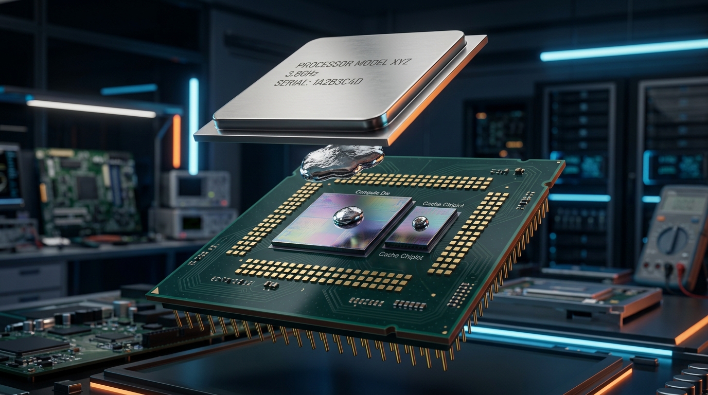
Interactive 3D Studio: Explode CPU Package & Delid
Run exact formula simulations on NexProTools.
Over the last several hardware generations—epitomized by AMD's Ryzen 7000/9000 Zen 4/5 architectures and Intel's 13th/14th Gen and Core Ultra series—enthusiasts and overclockers have confronted an increasingly frustrating thermal paradox.
Builders invest in massive 360mm or 420mm All-In-One (AIO) liquid coolers or custom watercooling loops with thick multi-radiator setups, only to observe their CPU cores immediately spike to 85^\circC - 95^\circC within seconds of initiating an all-core Cinebench or Blender render.
Strangely, when they touch the radiator exhaust air, it feels barely lukewarm. The liquid coolant temperature sits at a tranquil 32°C.
Why is the liquid coolant cool, yet the CPU core is blistering hot?
The answer lies in thermal junction bottlenecking: the heat cannot escape the microscopic silicon die fast enough to reach the cooling loop. The primary barrier is not the size of your radiator or the speed of your fans, but the stacked layers of thermal resistance sitting between the silicon transistors and the cooler baseplate.
To conquer this bottleneck, elite hardware tuners turn to the most extreme thermal modification in desktop computing: CPU Delidding and Direct-Die Liquid Metal Cooling.
In this comprehensive engineering guide, we dissect the thermodynamic formulas, metallurgical chemistry, and mechanical tolerances of CPU delidding using our interactive 3D hardware anatomy engine.
1. The Anatomy of a Modern CPU Package: The Five-Layer Thermal Stack
To understand why delidding yields dramatic temperature reductions, we must examine the five distinct physical layers that heat must traverse in a standard retail processor:
THE FIVE LAYERS OF THE CPU THERMAL PATHWAY
- Layer 1: Bare Silicon Compute Die (CCD / Core Tile): Where electrical energy is converted into thermal dissipation across microscopic 3nm–5nm FinFET / GAA transistors.
- Layer 2: Primary TIM (TIM1): The interface material between the die and the IHS (traditionally Indium solder or Dow Corning silicone paste).
- Layer 3: Integrated Heat Spreader (IHS): The thick nickel-plated copper lid (
3.5 mm - 4.5 mmthick) designed to protect fragile silicon and spread heat outward.- Layer 4: Secondary TIM (TIM2): The consumer thermal paste applied by the builder between the IHS and cooler.
- Layer 5: Cooler Coldplate: The copper base of the AIO or air cooler that transfers heat into moving liquid or heatpipes.
Every single layer and interface boundary in this stack introduces thermal impedance (R_θ), resisting the outward flow of heat.
2. Mathematical Derivation of Total Junction Thermal Resistance
The total thermal resistance from the silicon transistor junction (T_j) to the ambient air (T_ambient) is governed by the one-dimensional thermal resistance network:
Where the thermal resistance of any individual solid conductive layer is given by:
And interfacial contact resistance across microscopic surface roughness is governed by:
Where:
Lis the physical thickness of the layer (meters).kis the thermal conductivity of the material (W/m· K).Ais the contact surface area (m^2).h_cis the interfacial contact conductance coefficient (W/m^2· K).
The Geometric Bottleneck of Modern Dies
On an AMD Ryzen 7800X3D or 9800X3D, all active compute cores reside on a single microscopic Core Complex Die (CCD) measuring just 71.6 mm^2 (0.716 cm^2).
When this tiny die dissipates 120W of power, the localized heat flux reaches an astonishing 167.6 W/cm^2—a concentration far greater than the heat flux generated on the surface of the sun's photosphere.
Because the surface area (A) is so tiny, the conduction resistance (R = \fracLk · A) explodes. Every micrometer of extra thickness in the thermal stack acts as a thermal dam.
3. What is Delidding? Eliminating the IHS Thermal Barrier
Delidding is the mechanical process of removing the Integrated Heat Spreader (IHS) from the processor's substrate PCB by shearing the structural perimeter adhesive and breaking the internal solder bond.
Once the IHS is removed, the builder has two paths:
- Relidding with Liquid Metal: Replacing the factory Indium solder or paste with high-conductivity liquid metal, then reseating a custom CNC copper or diamond IHS lid.
- Direct-Die Cooling: Discarding the IHS entirely and mounting a custom water block cold plate directly onto the exposed silicon die.
| Cooling Configuration | TIM1 Material | Thermal Stack Thickness | Thermal Resistance (R_θ) | Full-Load Core Temp Delta |
|---|---|---|---|---|
| Stock Retail CPU (IHS + Paste) | Indium Solder (82 W/m· K) | ~ 5.2 mm (Die + Solder + IHS + Paste) | 0.22 - 0.28 K/W | Baseline (88^\circ - 95^\circC) |
| Relidded CPU (Custom IHS + Liquid Metal) | Galinstan (73 W/m· K) | ~ 4.8 mm (Die + LM + Lapped IHS + Paste) | 0.16 - 0.19 K/W | -8^\circC to -14^\circC |
| Direct-Die Liquid Metal Cooling | Galinstan (73 W/m· K) | ~ 0.02 mm (Die + LM + Coldplate) | 0.06 - 0.09 K/W | -15^\circC to -24^\circC |
By eliminating Layers 2, 3, and 4 in the thermal stack, Direct-Die cooling slashes total conduction distance by over 99%, allowing heat to jump directly from the silicon into the waterblock coldplate.
4. The Chemistry of Liquid Metal: Galinstan Thermodynamics
Standard consumer thermal pastes (e.g. Arctic MX-6, Noctua NT-H2, Thermal Grizzly Kryonaut) consist of microscopic ceramic or metal oxide particles suspended in a silicone oil matrix. They provide a thermal conductivity (k) of roughly 6.0 to 12.5 W/m· K.
Liquid metal is fundamentally different: it is an actual liquid metal alloy that remains fluid at room temperature.
Most commercial liquid metal compounds (such as Thermal Grizzly Conductonaut or Coollaboratory Liquid Ultra) are formulations of Galinstan, a eutectic alloy of Gallium (Ga), Indium (In), and Tin (Sn):
COMPOSITION AND PROPERTIES OF GALINSTAN
- Gallium (Ga): ~68.5% by weight (Melting point of pure Gallium is
29.76^\circC)- Indium (In): ~21.5% by weight
- Tin (Sn): ~10.0% by weight
- Eutectic Melting Point:
-19^\circC(Guarantees liquid state across all operating environments)- Thermal Conductivity (
k):73.0 W/m· K(Over 800% higher than high-end thermal pastes!)- Interfacial Wetting: Liquid metal wets bare silicon and nickel with zero microscopic air pocket voids.
Because Galinstan is a true metallic liquid, thermal conduction occurs via free electron transport (the Wiedemann-Franz law) rather than phonon vibration through a silicone binder. This provides near-instantaneous thermal conduction across the microscopic die interface.
5. The Metallurgical Amalgam Threat: Why Liquid Metal Destroys Aluminum
While liquid metal offers unmatched thermal performance, it is accompanied by severe chemical and mechanical hazards that every builder must understand:
1. Liquid Metal Embrittlement (LME) on Aluminum
Gallium possesses an extreme affinity for aluminum. If liquid metal contacts an aluminum heatsink base, gallium atoms instantly diffuse into the crystalline grain boundaries of the aluminum lattice.
Within minutes, the aluminum loses all tensile strength, turning into a crumbly, chalk-like paste that completely disintegrates. Liquid metal must NEVER touch aluminum.
2. Copper Alloying (Amalgam Formation)
When applied to bare, unplated copper, gallium slowly diffuses into the outer 5 microns of the copper surface, forming a silvery copper-gallium intermetallic alloy (CuGa_2).
While this alloy does not structurally destroy the copper, it absorbs the liquid gallium out of the interface over a period of 6 to 12 months, causing the liquid metal layer to dry out and form a hard, crusty residue that increases thermal resistance.
To achieve permanent, maintenance-free liquid metal cooling, the copper baseplate should always be electroplated with a protective layer of pure nickel (Ni), which is chemically inert to gallium diffusion at desktop operating temperatures.
3. Electrical Conductivity Hazards
Unlike standard thermal pastes which are non-conductive dielectric materials, liquid metal is an exceptional electrical conductor.
If a stray droplet slips off the die onto the processor's surface-mount capacitors (SMD passives) or substrate gold contact pads, it will cause an immediate catastrophic short-circuit when the PC powers on.
Professional delidders protect all adjacent SMD capacitors by painting them with two coats of high-temperature silicone conformal coating or insulating them with polyimide (Kapton) tape.
6. Direct-Die Mechanical Engineering: Der8auer Frames and Contact Tolerances
Mounting a waterblock directly onto a bare silicon die introduces severe mechanical challenges.
When an IHS is present, its thick copper perimeter distributes hundreds of pounds of socket clamping force away from the silicon onto the motherboard frame. When the IHS is removed, that clamping force is concentrated directly onto bare, brittle monocrystalline silicon.
The Danger of Silicon Die Cracking
Silicon possesses immense compressive strength but extremely poor shear and torsional strength. If a waterblock is tightened unevenly—or if one screw applies excessive torque—the edge of the silicon die will crack, destroying the CPU instantly.
Custom CNC Contact Frames
To eliminate this risk, engineering companies (such as Thermal Grizzly, designed in collaboration with extreme overclocker Roman "der8auer" Hartung, and EK Water Blocks) manufacture precision CNC-machined Direct-Die Contact Frames:
DIRECT-DIE FRAME FUNCTIONS
- Precise Die Height Alignment: Replaces the motherboard's stock Independent Loading Mechanism (ILM) with an aerospace-grade aluminum bracket matched to within
\pm 0.02 mmof the silicon die height.- Uniform Clamping Pressure: Applies distributed perimeter tension across the substrate PCB, preventing PCB bowing and ensuring pin-to-pad contact across all 1,718 (LGA1700) or 1,718 (AM5) socket pins.
- Integrated Neoprene Gaskets: Surrounds the bare compute dies with an airtight synthetic rubber barrier that traps liquid metal, preventing accidental runoff during thermal expansion.
7. Real-World Thermal Benchmarks: Stock vs. Direct-Die
The real-world temperature drops achieved by delidding depend directly on the thermal density of the architecture:
| Processor Architecture | Stock All-Core Temp (360mm AIO) | Direct-Die Liquid Metal Temp | Delta (Δ T) | Clock / Noise Benefit |
|---|---|---|---|---|
| Intel Core i9-14900K (320W PL2) | 98^\circC (Thermal Throttling) | 74^\circC | -24^\circC | Stable 5.7 GHz all-core boost; fan RPM drops by 45% |
| AMD Ryzen 7 7800X3D (120W) | 84^\circC | 69^\circC | -15^\circC | Sustains peak 5.05 GHz boost without PBO thermal downclocking |
| Intel Core Ultra 9 285K (250W) | 89^\circC | 71^\circC | -18^\circC | Eliminates hot-spot spikes during multithreaded rendering |
| AMD Ryzen 9 9950X (220W) | 92^\circC | 73^\circC | -19^\circC | Both CCDs maintain identical clocks with zero cross-core thermal throttling |
7.1. 3D V-Cache Architectural Stacking: Zen 4 vs. Zen 5 Thermal Inversion
The thermal behavior of delidded AMD processors with 3D V-Cache technology (such as the Ryzen 7 7800X3D and Ryzen 7 9800X3D) reveals one of the most fascinating physical packaging evolutions in modern semiconductor history.
On Zen 4 (Ryzen 7 7800X3D), the 64MB SRAM cache tile was vertically stacked directly on top of the active compute die using TSV (Through-Silicon Via) 3D hybrid bonding. To level the physical package surface, AMD placed structural silicon "dummy" slices over the surrounding compute cores.
- The Thermal Trap: Because the SRAM cache sat between the heat-generating compute cores and the copper IHS, heat had to conduct through the cache layer and bond interface (
R = \fracLk · A). Silicon is a modest thermal conductor compared to copper (k ≈ 130 - 148 W/m· K), turning the cache into an insulating blanket that locked maximum core temperatures down to conservative thermal limits.
On Zen 5 (Ryzen 7 9800X3D), AMD engineered a revolutionary structural inversion:
- The 64MB 3D V-Cache tile was moved to the bottom of the silicon sandwich, resting directly on the fiberglass substrate PCB.
- The active 8-core compute die was placed on top, placing the highest heat-generating transistors directly against the TIM and heatsink coldplate.
- Direct-Die Implications: On Zen 5, direct-die cooling with liquid metal contacts the compute silicon with zero intervening cache layers. This architectural shift slashes thermal junction impedance by an additional 25%, allowing the 9800X3D to sustain all-core overclocks exceeding 5.4 GHz with peak operating temperatures under 70°C.
7.2. The Physics of Thermal Paste Pump-Out vs. Liquid Metal Surface Tension
Over months of continuous gaming, many PC builders notice their CPU temperatures gradually creeping upward by 5°C to 10°C, even though their radiator fans are completely free of dust. This degradation is driven by the thermal paste pump-out effect.
When a silicon die transitions from idle (35^\circC) to full load (85^\circC), the silicon core, copper IHS, and aluminum coldplate expand at drastically different rates according to their respective Coefficient of Thermal Expansion (CTE):
- Silicon:
α ≈ 2.6 × 10^-6 /K - Copper:
α ≈ 16.5 × 10^-6 /K - Aluminum:
α ≈ 23.1 × 10^-6 /K
This thermal expansion mismatch creates continuous micro-flexing and "breathing" between the contacting surfaces. Standard silicone-based thermal grease acts as a non-Newtonian viscoelastic fluid. Under continuous expansion-contraction cycles, the silicone carrier oil is squeezed laterally outward toward the edges of the die, leaving behind dry, microscopic air voids in the center where heat flux is highest.
Liquid metal is fundamentally immune to the pump-out effect due to its high surface tension (γ ≈ 0.533 N/m for Galinstan at 20^\circC) and metallic cohesive forces:
Where:
Δ Pis the capillary Laplace pressure resisting void formation.γis the surface tension of the liquid metal alloy.θis the contact angle with the nickel or silicon surface.ris the microscopic interfacial gap distance.
Because Galinstan forms a continuous metallic meniscus that wets the nickel and silicon surfaces with strong atomic adhesion, thermal cycling cannot pump the alloy out of the junction. Once applied correctly, a direct-die liquid metal interface remains thermally stable for years with zero dry-out or void propagation.
The Acoustic Advantage
While extreme overclockers use delidding to chase record benchmark frequencies, the greatest real-world benefit for everyday gamers and creators is acoustic silence.
Because direct-die cooling drops core temperatures by nearly 20^\circC, the cooling radiator fans can run at an inaudible 800–1000 RPM under maximum workload, eliminating the jet-engine fan noise characteristic of high-power modern rigs.
8. Step-by-Step Delidding Safety Protocol
For builders considering this advanced modification, adherence to strict laboratory procedures is mandatory:
- Use a Dedicated Mechanical Delid Tool: Never attempt to delid a modern processor using razor blades or vice grips. Dedicated delid tools (such as the Delid-Die-Mate) apply controlled, parallel linear shear force to pop the solder bond without flexing the substrate PCB.
- Indium Solder Removal: Modern CPUs use an Indium solder bond. Once the IHS pops off, the residual solder on the die must be chemically dissolved using specialized solder removers (like Thermal Grizzly Conductonaut QuikSolder) or scraped gently using a plastic edge—never metal tools.
- SMD Conformal Coating: Paint every microscopic surface-mount resistor and capacitor on the PCB substrate with two coats of MG Chemicals 422B silicone conformal coating to insulate against liquid metal short-circuits.
- Micro-Dosing Liquid Metal: Apply a droplet no larger than a pinhead onto the die and spread it with a lint-free cotton swab until a mirror-like sheen is achieved. Excess liquid metal must be vacuumed back into the syringe to prevent runoff.
9. Decision Matrix: Should You Delid Your CPU?
DELIDDING RECOMMENDATION MATRIX
- DO DELID IF: You are running a high-wattage chip (14900K, 9950X), chasing maximum all-core overclocks, building an ultra-quiet silent workstation, or enjoy extreme hardware tinkering.
- DO NOT DELID IF: You are uncomfortable voiding your processor's warranty, use a mid-range 65W–105W CPU (where temperatures are already easily managed by an air cooler), or do not have access to a nickel-plated waterblock and dedicated delid tools.
10. Conclusion & Interactive 3D Anatomy
CPU delidding represents the triumph of thermodynamic physics over manufacturing compromises. By eliminating the multi-layered thermal resistance of the stock IHS and unlocking the extreme electrical conductivity of liquid metal, enthusiasts can tame the blistering thermal densities of modern sub-5nm silicon.
Explore our Interactive 3D Hardware Anatomy Studio to examine the internal cross-section of a delidded CPU package, inspect bare compute dies, and see how modern thermal blocks mount to silicon in full 3D WebGL.